Software
Inkscape 0.92.3Flatcam
WinPc_nc 1.0.2
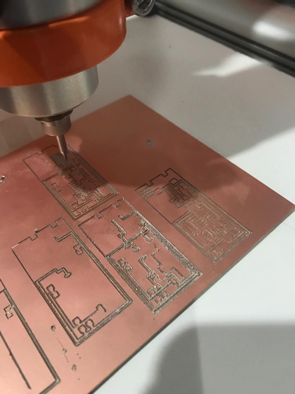
For milling the board we used a step craft milling machine and the material of the board we used copper clad 5 by 4inch.
Group assignment(Click here to read more about the group assignment.)
For our group assignment we must characterize the design rules for our PCB production process.We first setup our stepcraft milling machine to mill the copperclad for us.We also used the schematic png from the Fab Academy site.
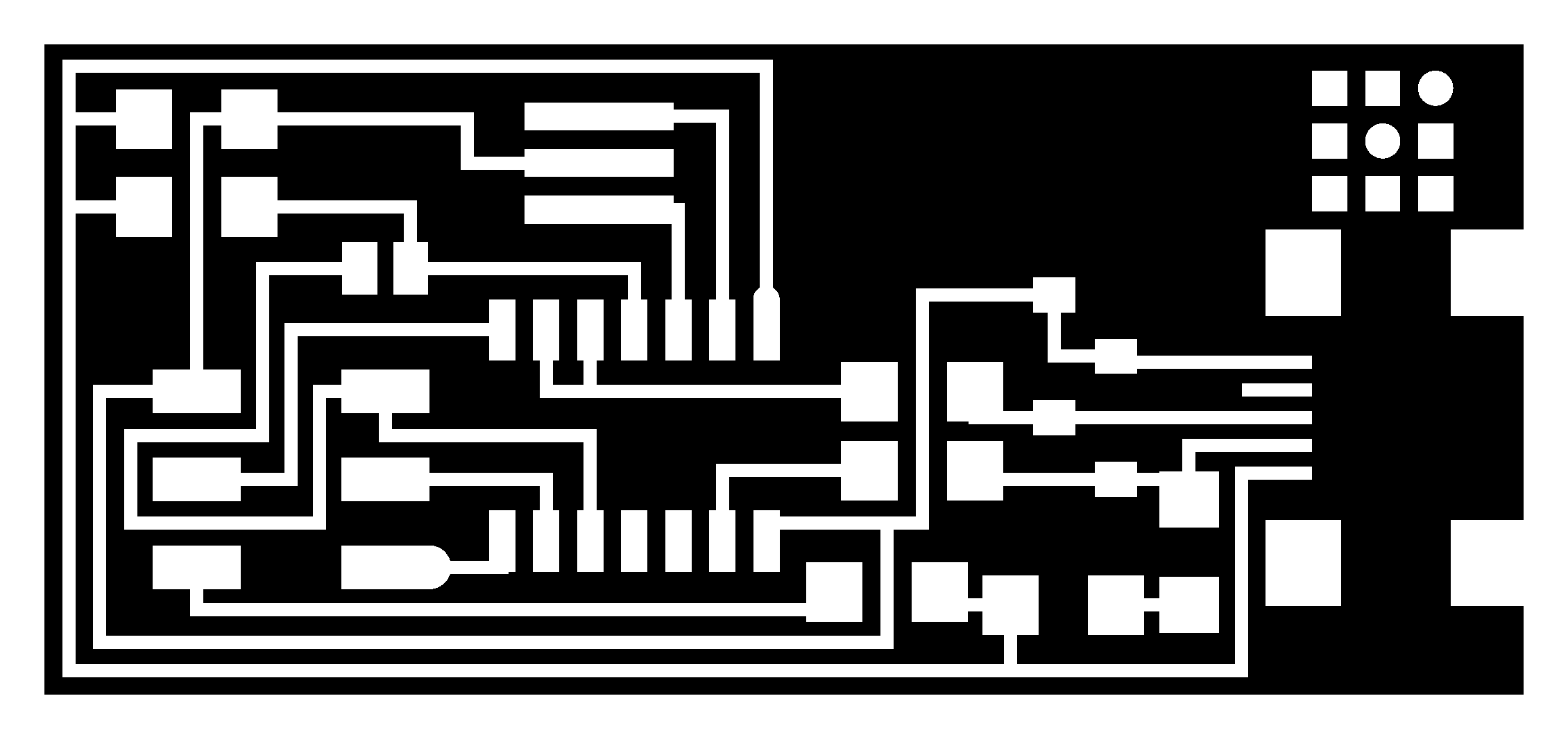
The PNG file we used to mill our boards
Invidual assignment
For our invidual assignment we needed to make an in-circuit programmer by milling it,solder the components on the board and program it.
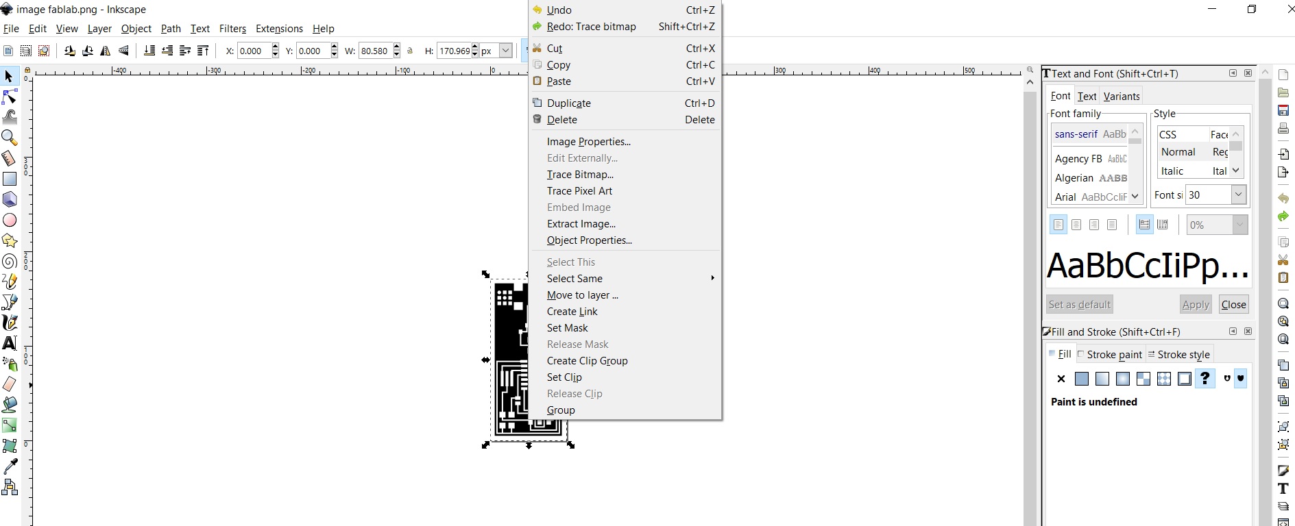
Download inkscape and Open the png file in Inkscape and bitmap your picture and then delete the original layer.
After deleting the orignal layer,your design has to look like this
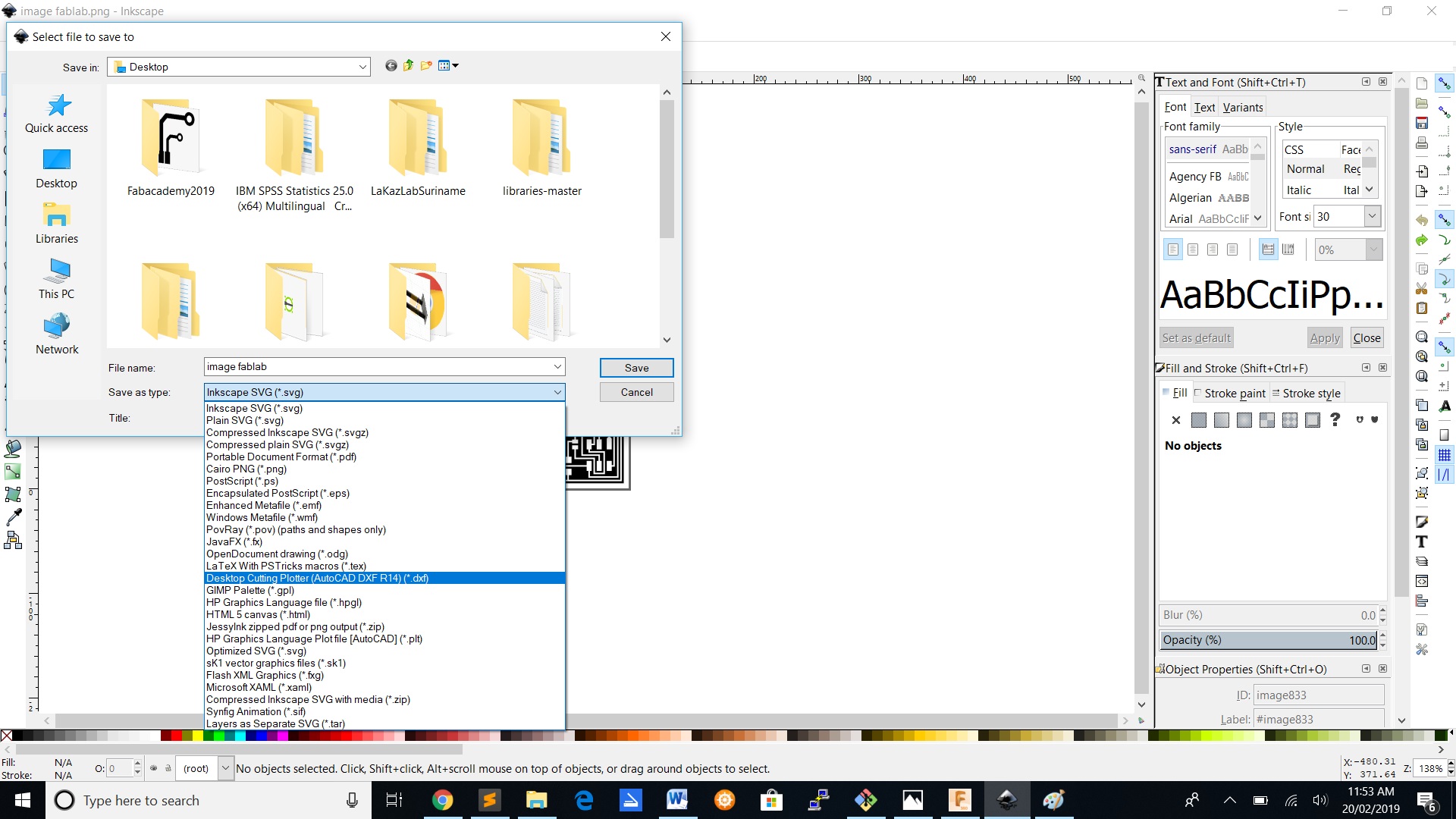
After deleting the original layer,you have to safe the file in .dxf format.
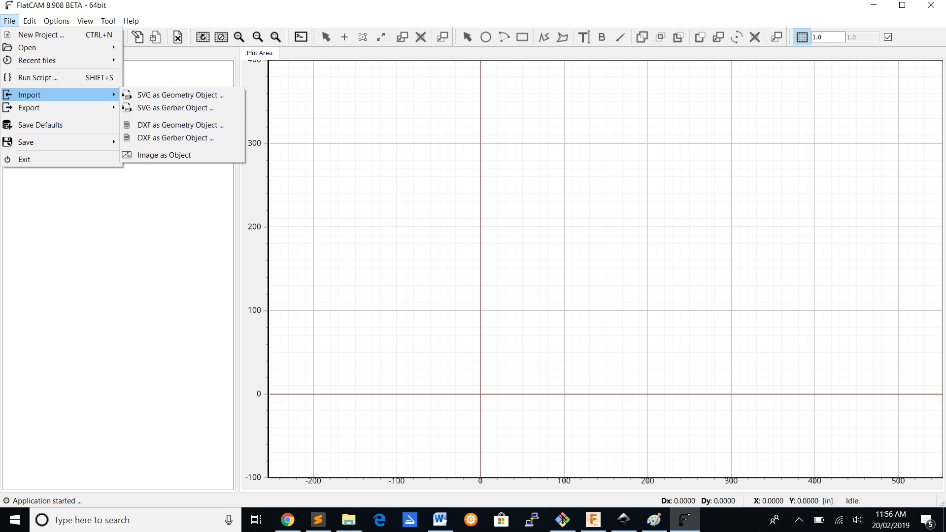
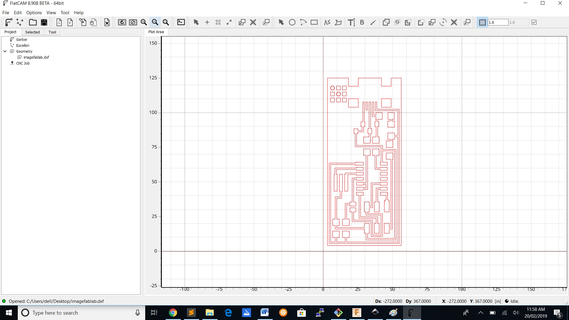
Import the .dxf file in flatcam by clicking on file ->import-> dxf geometry.
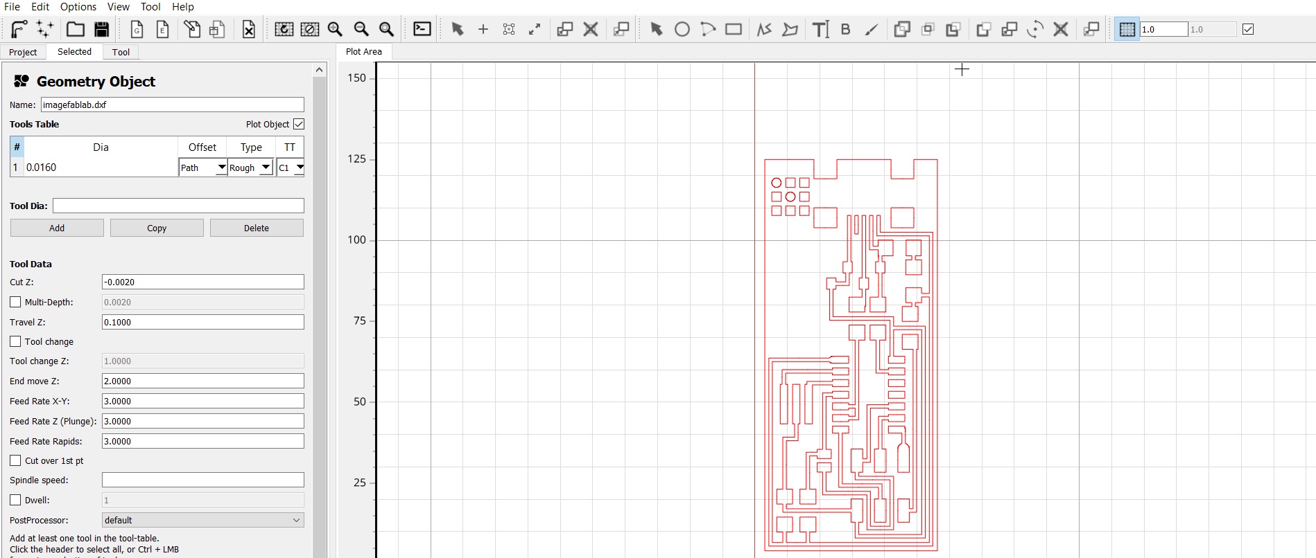
Before exporting your file to WinPc-Nc,you have to add values to the geometry from the object.
| Parameter | Value |
|---|---|
| Cut z | -0.15mm |
| Spindle speed | 12000 rpm |
| Feedrate | 0.5mm |
| Travel z | 2.5mm |
| Tooldia | 0.4mm |
G-code and WinPc-nc
G-code are used to determine the geometry of tool movements and operating state of the machine controller; functions such as linear cutting movements, drilling operations and specifying the units of measurement.WinPC-NC is a software program which turns any personal computer running the Windows operating system into a universal NC controller.
After adding the geometry in flatcam and selecting top copper for cutting the traces on the board.You have to generate the prarameters so that you can save your file in .nc format.After saving your file ,you have to open your file in winpc-nc.
.png)
Click on the parameter and select on tools ->In activation Add the spindle speed.In this case the spindle speed was 12000 rpm
.png)
Then in speeds at the value for the plunge,the advance,the withdrawal and the brake angle.The values are:
1.Plunge =0.10mm
2.V-advance =0.50mm
3.V-withdrawel =1.00mm
4.Brake angle =30mm
.png)
For dimension you need to add value at the first cut depth.The value for the first cut depth is 0.10mm
There also parameters that has to change in the Winpc-nc.Check the selection box of invert-z,also need to change the origin of the coordinates and also to go back to the zero point at the end.
To attach the board to the milling machine we used double sided tape.
After attaching the board to the mill ,you have to search for the zero x,y and z.For doing that you have to work with the jog from the winpc-nc.You also have to be very carefully when searching for the zero on the z-axis because of the bit.If you don't do it carefully you can break or damage the bit.

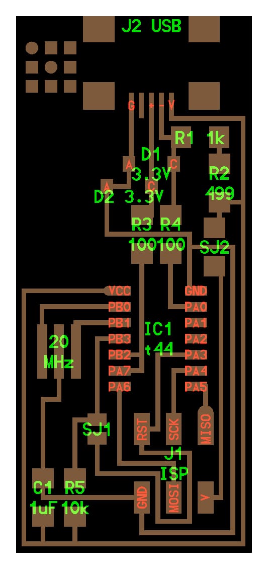
The components that needs to be solder on the board are :
- Atiny 44a
- 2*diode
- 1k resistor
- AVRISP 2*3pins
- 10k resistor
- 4990ohm resistor
- 1* Resonator 20MHZ
- 1k resistor
- 1* 1uF Capacitor
- Usb connector
- 2* 0ohm resistor
- 10kOhm Resistors
Solder the components to the board
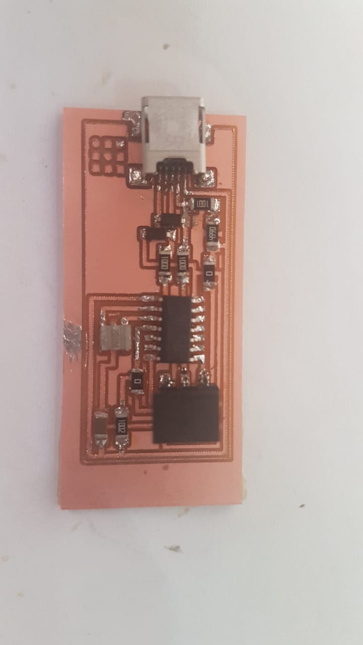
After Soldering the components the board should look like this.
Porgramming
The issue we had for programming the board i that we couldn't flash the board in windows.It went wel in Ubuntu.
Making another ISP Programmer
There were alot of issues with the other board so we decided to create another ISP programmer.So we took Brian's design on the Academy site and tried it.Here is the link to the design Brian's ISP programmer.
The proces to milling the board is the same as the other ISP board.The design looks like this :
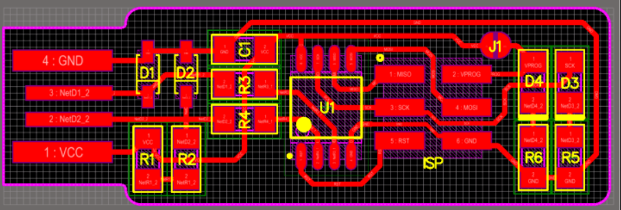
This Programmer has :
1x ATtiny45
2x 1kΩ resistors
2x 499Ω resistors
2x 49Ω resistors
2x 3.3v zener diodes
1x red LED
1x green LED
1x 100nF capacitor
1x 2x3 pin header
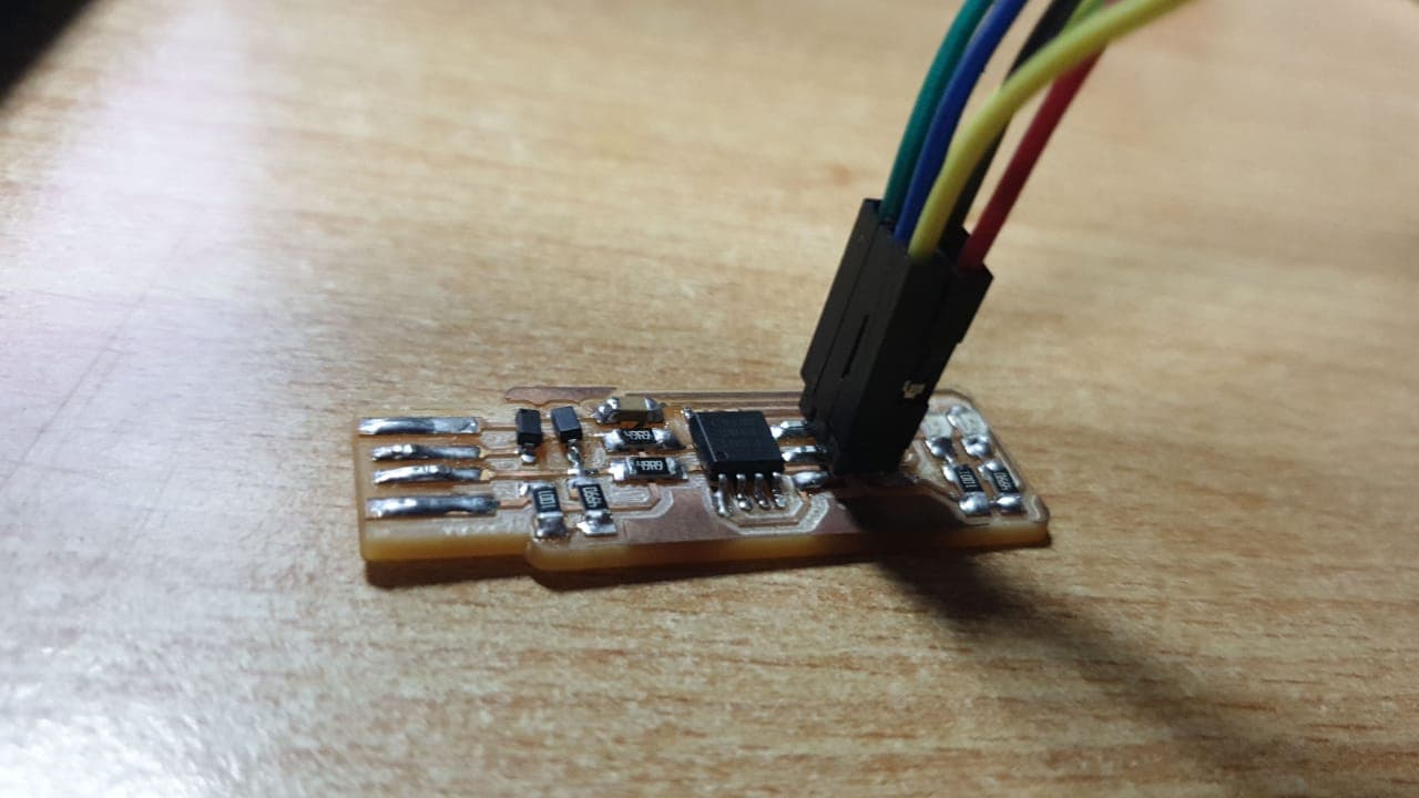
After soldering the board will look like this
Programming the board
For programming the board i used Ubuntu software and the another ISP programmer.I followed the steps which are given at Brian's page and run the steps in the terminal.The steps for programming the board on Ubuntu is :
1.Download firmware source code
For downloading the firmware source code Click here.2.Run make
3.Run makefile
4.Run make flash
5.Run make fuses
6.Test the board
After doing those steps you can use your programmer to program other boards
.png)
.png)
.png)
Files
Flatcam ISPFlatcam ISP cut trace
Flatcam PCB